Permanently Installing a V1 Radar Detector
[cdeegbjij]
Other Xoc managed sites:
http://www.xoc.net
http://grr.xoc.net
http://www.mayainfo.org
https://mayacalendar.xoc.net
http://www.yachtslog.com
Running the Wires
To permanently mount the Valentine One (V1) radar detector, several techniques have been used. The one described here is the one that the editor recommends.
Parts and Tools
- V1 Detector
- Jack for V1
- Concealed display for V1
- Remote volume control for V1 (optional, available from Valentine Research)
- 6' Telephone cord
- 2' Telephone cord
- 2' Telephone cord (for optional volume control)
- Fabricated facing for displays (described below)
- T20 torx driver
- T25 torx driver
- Adjustable wrench or vice grips
Assure that all the telephone cord is four wire. Some telephone cord for answering machines and such only come with two wires. You can use longer lengths of telephone cord, but not shorter. You can make telephone cords of the correct length by acquiring a crimping tool, some raw cord, and the plugs from your local Radio Shack.
Steps
- Remove the carpet covered side access panels from the front console. Do this by grabbing
the edge that is deepest into the footwells and pulling toward the side of the car until
the snaps come free. Then slide the carpet panels further into the footwell to disengage a
(fragile) tongue slides into a groove.
- Pull the forward side panels free. Do this by grasping the side deepest into the
footwells and pulling toward the side of the car until the snap pulls free. Then slide
toward the front of the car until disengaged.
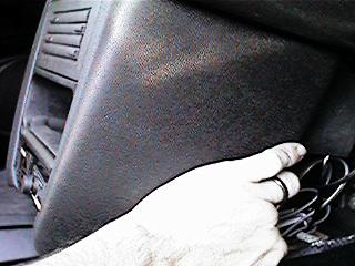
- Remove the "bat-shaped" housing at the bottom of the console, just above the
shift boot by simply pulling straight out.
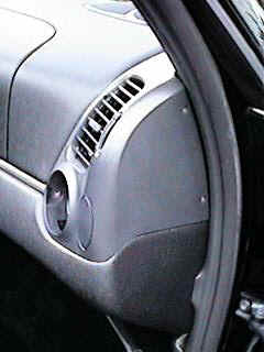
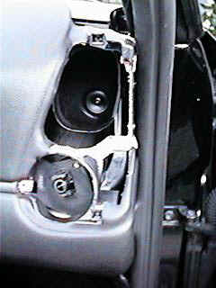
- Remove the passenger side air vent. Do this by popping off the round grill held by
friction. Then unscrew the T20 torx screw in the grill and the two torx screws on the
side. Then pull the air vent free.
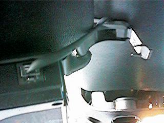
- Remove the passenger side sun visor. Do this by removing the two T25 torx screws and the
T20 torx screw hidden under the plastic flap.
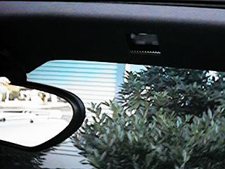
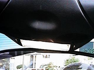
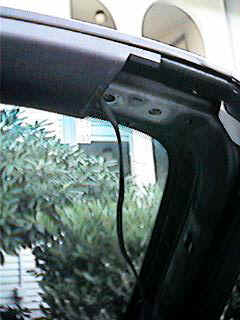
- Loosen the top plastic molding. Do this by popping off the two plastic caps over the
infra-red sensors for the alarm, then loosening the two T25 torx screws inside.
- Remove the side plastic molding. Do this by simply pulling straight up.
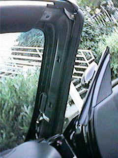
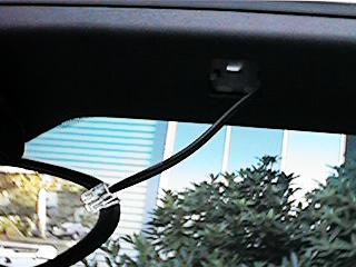
- Thread the six foot phone cord through the hole where the left hand side of the sun
visor connects. Allow about four inches of extra cord to be available. Allow about six
inches if you intend to attach to the suction cup mount instead of the visor mount shown
below.
- Route the cord under the plastic framework and down the side panel.
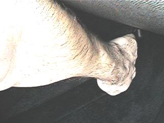
- Pull the foam housing from the bottom of the passenger footwell down.
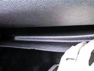
- Thread the cord through the air vent area and down into the passenger footwell.
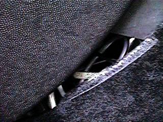
- Thread the cord along the top of the foam over to the central panel.
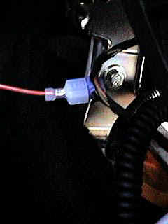
- Attach the jack to the hot wire. To do this find the wire harness that runs free under
in the area above the airbag control unit. In 1997 model year Boxsters, this is a
three wire harness. In 1998 and later Boxsters, this is a four wire harness. In either
case, you will need to tap into the black and green wire in the harness. Take the blue
leaching tap that comes with the V1 and fasten this around the black and green wire. Then
connect the jack to the tap.
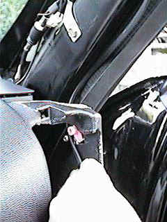
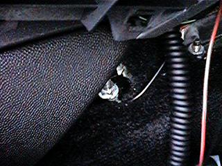
- Use the adjustable wrench or vice grips to loosen the bolt holding down the base of the
console. Then connect the ground wire from the jack to the bolt and tighten. It may take
considerable effort and leverage to get this bolt loosened.
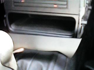
- Attach the two foot cord to the "Accessory" socket on the jack. Thread the other end though the back of the area where the "bat-shaped" piece was removed. Attach the other end of the cord to the concealed display.
- If you have the optional volume control, attach the second two foot cord to the
"Main Unit" socket of the jack. Thread the cord through the same access area and
attach to the volume control "Power In" socket. Thread the cord from the V1
through the access area and attach to the volume control "Power Out" socket.
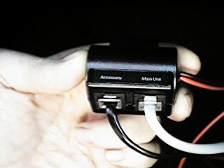
- If you do not have the optional volume control, just attach the cord from the V1 to the "main unit" socket of the jack.
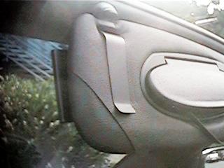
- Attach the V1 to the cord at the passenger visor.
- Turn on the V1 and optional volume control and set the volumes to their max.
- Turn on the ignition. The remote display should light, the start-up tones of the V1 should sound. If not, check all connections.
- Insert the remote display and volume control into the faceplate that you have had constructed (see below). Place the faceplate where the "bat-shaped" piece was.
- Reassemble all the interior hardware by reversing the procedures used to dismount it above.
- Insert the clip of the V1 holder into the hinge hole of the passenger visor and slide
the V1 onto it.
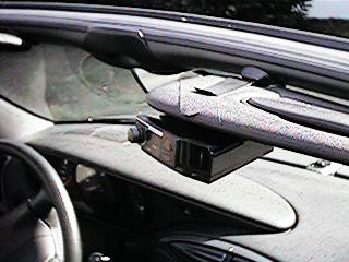
- Enjoy your permanently mounted V1. You may mute the detector either at the volume
control or at the main unit.
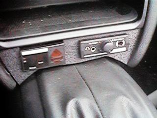
Constructing the Face Plate
The face plate was fabricated at a local plastics shop. The cost was $20 including shaping it and cutting the holes. I provided a template. The template design will be posted here in the next week or so.
Top
[www.986faq.com] Copyright © 1997-2023 by Gregory Reddick